The program MSA calculates the diffraction of fast electrons in an atomic structure with the multislice algorithm. The results can be complex-valued wave functions, STEM images, CBED patterns, or probe intensity distributions.
| Line | Parameters | Description (Version 0.62+) |
|---|---|---|
| 01 | <string> | Parameter block name, must be ‘[Microscope Parameters]’ |
| 02 | <float> | STEM probe forming aperture, radius [mrad], e.g. 25The line supports up to 4 numbers as input where the second number defines the relative asymmetry of an elliptical aperture, the third number defines the orientation of the asymmetry axis in radians, and the fourth number defines the relative smoothness of the aperture edge. Example: 25., 0.026, 0.34, 0.038, defines an aperture of 25 mrad mean radius with 2.6% asymmetry along 0.34 rad and 3.8% edge smoothness. |
| 03 | <float> | Inner radius of an annular diffraction detector [mrad], e.g. 80 |
| 04 | <float> | Outer radius of an annular diffraction detector [mrad], e.g. 250 |
| 05 | <number> <string> | Detector file usage, set the number to 0 for switching off (the annular detector defined in lines 3 and 4 will be used). Set the switch to 1 for using a detector parameter file and provide the file name with the string parameter. Example: 1, 'detectors.prm' |
| 06 | <float> | Probe electron wavelength [nm] or kinetic energy [keV], e.g. 0.001969 |
| 07 | <float> | Effective source radius (HWHM) [nm] (STEM only), e.g. 0.055 |
| 08 | <float> | Effective focus spread (1/e half-width) [nm] (STEM only), e.g. 1.5 |
| 09 | <float> | Focus-spread kernel width (relative to focus-spread) (STEM only), e.g. 2.0 |
| 10 | <number> | Number of focal kernel steps (STEM only), e.g. 7 |
| 11 | <number> | Number Nabr of aberration coefficients set below, e.g. 3 |
| 11 + | <number> <float> <float> | Aberration definition, index number and two coefficient values [nm] (details see right) Nabr aberration definitions are expected following line 11. By default, aberration coefficient values are all zero. You may set Nabr = 0 and leave out all aberration definitions. Note that depending on the number of aberration definitions Nabr, the following content is moved further lines down in the parameter file. |
| 12 + Nabr | <string> | Parameter block name, must be ‘[Multislice Parameters]’ |
| 13 + Nabr | <float> | Object tilt x component [deg], e.g. 0.5 |
| 14 + Nabr | <float> | Object tilt y component [deg], e.g. 0.0 |
| 15 + Nabr | <float> | Horizontal scan frame offset in the super-cell [nm], e.g. 0.0 |
| 16 + Nabr | <float> | Vertical scan frame offset in the super-cell [nm], e.g. 0.0 |
| 17 + Nabr | <float> | Horizontal scan frame size [nm], e.g. 1.24 |
| 18 + Nabr | <float> | Vertical scan frame size [nm], e.g. 0.785 |
| 19 + Nabr | <float> | Scan line (row) rotation with respect to the super-cell x-axis [deg], e.g. 15 |
| 20 + Nabr | <number> | Number of scan columns (row length), e.g. 124 |
| 21 + Nabr | <number> | Number of scan rows (column length), e.g. 79 |
| 22 + Nabr | <number> | Switch the explicit focus spread convolution OFF (0) or ON (1). |
| 23 + Nabr | <number> | Switch convolution by a source distribution function OFF (0), ON with Gaussian profile (1) or with Lorentzian profile (2). |
| 24 + Nabr | <number> | Super-cell repeat factor along x, e.g. 1.Values > 1 will increase the size of the wave function and the computation time. |
| 25 + Nabr | <number> | Super-cell repeat factor along y, e.g. 1.Values > 1 will increase the size of the wave function and the computation time. |
| 26 + Nabr | <number> | Super-cell repeat factor along z, e.g. 1.(not used anymore. Set it to 1!) |
| 27 + Nabr | <string> | Slice file name prefix, e.g. 'STO001_300kV'The program will look for files with this file name extended by '_###.sli', where ### is a 3 digit number and slice index. If one of the slice files is not found, the program will terminate with an error. |
| 28 + Nabr | <number> | Nsf = Number of slice files to be loaded, e.g. 4 |
| 29 + Nabr | <number> | Maximum number of frozen-phonon variants used, e.g. 50 |
| 30 + Nabr | <number> | STEM: Minimum number of frozen-phonon configurations to be averaged per scan pixel or CBED pattern, e.g. 1.CTEM: Minimum number of frozen-phonon configurations used to generate wave functions, e.g. 100.Warning: If wave functions are extracted from the multislice calculation, the number of wave functions that will be generated and stored in separate files is increased accordingly. A wave function file will be written for each applied frozen-phonon configuration. |
| 31 + Nabr | <number> | Period of readout or detection in units of slices, e.g. 2.This parameter determines the amount of readout during the multislice calculation. It is the sampling of output along the propagation direction and allows thus to generate output representing a sample thickness series. Set this value to zero if you are only interested in output at the maximum sample thickness defined in the line below. |
| 32 + Nabr | <number> | Nsl = Number of slices used to describe the full sample up to its maximum thickness, e.g. 64.The same number of lines is expected to follow below. This number determines the maximum thickness, corresponding to the sum of applied slice thicknesses. |
| 32 + Nabr + | <number> | Slice index, e.g. 0.This line and all following lines should contain only one number each. The numbers denote the slice index of from the list of loaded slice files as specified in the lines (27+Nabr) and (28+Nabr). Slice indices are numbers from 0 up to Nsf – 1, where Nsf is the number of loaded slice files specified in line (28+Nabr) above. An example sequence with 8 object slices realized with 4 loaded slice phase-gratings could be 0, 1, 2, 3, 0, 1, 2, 3. You are however completely free in choosing any possible sequence of slices to form the sample structure along the z direction. |
Control Files
The calculation setup and the physical parameters of multislice calculations with MSA are controlled by parameter files. The parameter files are text files containing lists of values and strings in fix sequences. You may generate your own parameter files or export an MSA parameter file from a setup done with the Dr. Probe graphical user interface.
The table given below describes the structure of the MSA main parameter file and gives a short description of the meaning for each parameter. The parameter file is a mandatory parameter when calling MSA and may link to a detector parameter file.
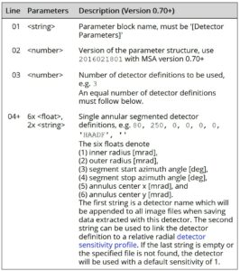
Detector File
In line 5 of the MSA parameter file you may link to another parameter file defining multiple detectors. A detector parameter file is also a text file listing a fix sequence of parameters. You may generate your own detector parameter file from the table below or by exporting a detector setup of the Dr. Probe graphical user interface.
The table given below describes the structure of the parameter file and gives a short description of the meaning for each parameter.
Detector Sensitivity
Information about the detector sensitivity can be found here.
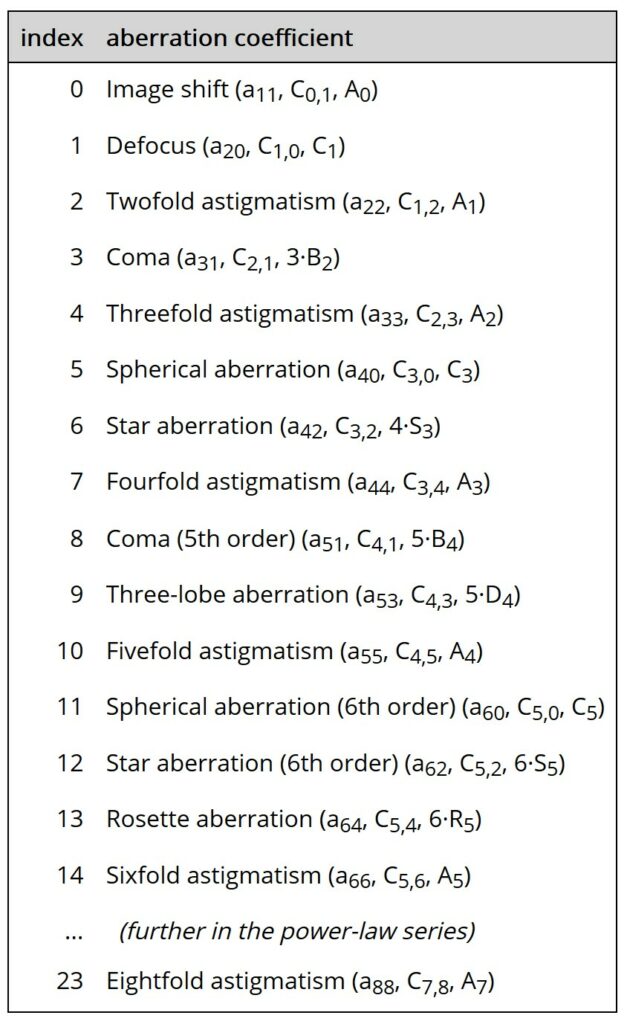
Aberration Indexing
The control files of the programs MSA and WAVIMG contain options to define the probe and imaging aberration states, respectively. The programs support aberration coefficients up to the 8th order. Descriptions are given here of how to define aberrations in these files.
Aberration definitions in the parameter control files are an index number followed by two coefficient values.
Examples:
– defocus of 5.8 nm: 1 5.8 0.0
– star aberration of 4.7 µm at 30°: 6 4070. 2350.
The index number (0 … 23) identifies the aberration type and the two values are the x and y components of the respective aberration coefficient in nanometer units. A complete aberration list is given below including typical coefficient notations.