
We describe here how to create atomic structure data for TEM and STEM image simulations in a different crystallographic orientation than the original structure model. The material in this example is the cubic perovskite SrTiO3, and we want to prepare structure data for imaging along the [110] zone-axis by using the two command-line tools BuildCell and CellMuncher.
Quick guide to structure file creation for multislice simulations
The steps required to create and adopt a structure model for STEM and TEM image simulations are listed here in short. More detailed explanations are given below.
1. Open the command-line shell and prepare a folder structure for storing data.
2. Create a unit-cell with BuildCell.
3. Orient (rotate) the unit-cell to the desired zone axis with CellMuncher.
4. Center the atoms in the structure slices by shifting along the c (z) axis. Shift atoms also away from the x and y boundaries of the cell.
5. Extend the cell (periodically) for frozen-lattice simulations.
Preparations
1. Start the console or command-line shell. On Windows OS you may use the Dr. Probe command-line shell or add the Dr. Probe installation folder to your environmental PATH variable.
2. Create a working directory for storing data, e.g. C:\data\sto\110\.
3. Switch to this directory within the command-line shell by typingcd C:\data\sto\110
4. Create a sub-folder which will hold the structure data by typingmd cel
If you prefer organizing your files in a different way, adopt the file names below accordingly.

The structure parameters are taken from Abramov et al. [1].
Creating a SrTiO3 unit-cell
Crystal unit cells can be created with the tool BuildCell. For the case of SrTiO3 we fill a primitive cubic cell with atoms and assign thermal vibration parameters. For such simple unit cells you may alternatively write the CEL file manually.
BuildCell --spacegroup=221 --lattice=3.901,3.901,3.901,90.0,90.0,90.0
        --atom=Sr,0.0,0.0,0.0,1.0,0.62 --atom=Ti,0.5,0.5,0.5,1.0,0.44
        --atom=O,0.0,0.5,0.5,1.0,0.71 --output=cel\STO_001.cel
The result is written into the file cel\STO_001.cel and should look like the text below. (Download)
Orientation of the unit cell along [110]
Orient the unit cell along the [110] zone axis using the --create-block option of CellMuncher. Take care to extend the periodic unit, such that the tilted structure is again periodic in an orthorhombic cell along the new crystal axes. This is simple for initially cubic cells as in the present case. The new cell dimensions along x and z will be by a factor of square root of 2 larger than the cubic cell: a’ = c’ = a * Sqrt(2). Use at least 6 digits precision for the new cell dimensions in order to prevent round-off problems.
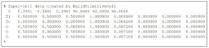
CellMuncher -f cel\STO_001.cel -o cel\tmp1.cel --create-block=1,1,0,0,0,1,0.55168472,0.3901,0.55168472

The size of the new cell is a’=0.55168472nm, b’=0.3901nm, c’=0.55168472nm and it contains 2 of the original SrTiO3 units, i.e. 2 Sr atoms, 2 Ti atoms and 6 O atoms.

Center atomic planes to structure slices
The current super-cell file cel\tmp1.cel should look as in the image above but may contain more than the desired 10 atoms (= 2 original unit SrTiO3 cells) due to round-off errors during the block cutting.
Next, we translate all atoms by half an atomic plane along each cell dimension. This step prevents later possible numerical round-off errors, e.g. during the subsequent distribution of the super-cell atoms into 4 equidistant slices along z. The translation by half atomic planes should be done always, when atoms are placed at the termination planes of object slices.
For the current example of SrTiO3 [110] the fractional shifts by half planes along each axis are (0.125, 0.25, 0.125). Note that other structures will require different fractional shifts. The fractional shift should be 1/(2Np), where Np is the number of atomic planes along a cell axis.
CellMuncher -f cel\tmp1.cel -o cel\tmp2.cel -T x,0.125 -T y,0.25 -T z,0.125
We now wrap the fractional atomic site coordinates back to the interval [0,1).
CellMuncher -f cel\tmp2.cel -o cel\tmp3.cel --periodic=x --periodic=y --periodic=z --cif
Previous round-off errors occurring with block cutting will now be cured by removing atoms which are closer than a small threshold distance to other atoms. As threshold, usually 0.2 Å are sufficient.
CellMuncher -f cel\tmp3.cel -o cel\STO_110.cel --remove-close-atoms=0.2 --cif
The result of the above procedure up to this point is shown in the figure on the left.
This super-cell can be the input for a coherent TEM image calculation using Debye-Waller factors to describe thermal diffuse scattering (TDS).
Download the SrTiO3 [110] super-cell for TEM simulations.
For STEM image simulations or TEM image simulations approximating TDS by a frozen lattice (frozen phonons) approach, please proceed to the next step!
Extend the super-cell by 3 x 4
We repeat the SrTiO3 [110] super-cell 3 times along x and 4 times along y.
CellMuncher -f cel\STO_110.cel -o cel\STO_110_3x4.cel --repeat=x,3 --repeat=y,4 --cif
The size of the new super-cell is now a = 1.6569 nm, b = 1.562 nm, and c = 0.5523 nm, and it contains 24 of the original SrTiO3 unit cells projected along the [110] zone-axis.
An increased x– and y-dimension of the super-cell allows us to introduce aperiodic atomic displacements in a frozen-lattice approach. It should be done if severe artifacts can be expected due to the real-space wrap-around of the spreading wave function with increasing object thickness. You should adopt the number of repeats to your simulation. As a general rule of thumb: calculations for thicker objects require also a larger super-cell along x and y.
An image of the 3×4 extended SrTiO3 [110] super-cell is shown in the figure on the right.
The extended super-cell can be used for small-scale STEM image simulations. It should give reasonable results for a specimen thickness below 40 nm.
Download the extended SrTiO3 [110] super-cell for STEM simulations.

Summary of commands:
Following is the complete sequence of all commands used above. You may copy this sequence and execute it by one call from a batch file or shell script.
BuildCell --spacegroup=221
--lattice=3.901,3.901,3.901,90.0,90.0,90.0
--atom=Sr,0.0,0.0,0.0,1.0,0.62 --atom=Ti,0.5,0.5,0.5,1.0,0.44
--atom=O,0.0,0.5,0.5,1.0,0.71 --output=cel\STO_001.cel
CellMuncher -f cel\STO_001.cel -o cel\tmp1.cel --create-block=1,1,0,0,0,1,0.551685,0.3901,0.551685
CellMuncher -f cel\tmp1.cel -o cel\tmp2.cel -T x,0.125 -T y,0.25 -T z,0.125 --cif
CellMuncher -f cel\tmp2.cel -o cel\tmp3.cel --periodic=x --periodic=y --periodic=z --cif
CellMuncher -f cel\tmp3.cel -o cel\STO_110.cel --remove-close-atoms=0.2 --cif
CellMuncher -f cel\STO_110.cel -o cel\STO_110_3x4.cel --repeat=x,3 --repeat=y,4 --cif
Translation from CEL to CIF for visualization
Use the command
CellMuncher -f dummy-file-name.cel -o dummy-file-name.cif -w CIF
for translating from the CEL file format to CIF. You can open the resulting CIF file directly with the program VESTA to visualize the structure.
Note that the Biso values in the CIF output of CellMuncher is on a wrong scale. Correct these values before using the CIF file in simulations.
References
[1] Yu.A. Abramov, V.G. Tsirel’son, V.E. Zavodnik, S.A. Ivanov, and I.D. Brown, Acta Cryst. B 51 (1995) p. 942. doi: 10.1107/S0108768195003752